Product Review ** JETI HiCopter 30A Opto ESC

econfly

Member
JETI HiCopter 30A Opto ESC Review

PART 1: OVERVIEW

JETI_zpsabc8facc.jpg


In the simplest sense, what we want to know most about an ESC is whether it works. So let's deal with this most essential question first: Yes, these HiCopter ESCs work just fine. I plugged them into a test quad with a Naza v2 flight controller. In light wind everything worked as expected with stock gains and no issues whatsoever.

Feel free to skip the video. There is truly nothing unusual to see here.

https://vimeo.com/96621915

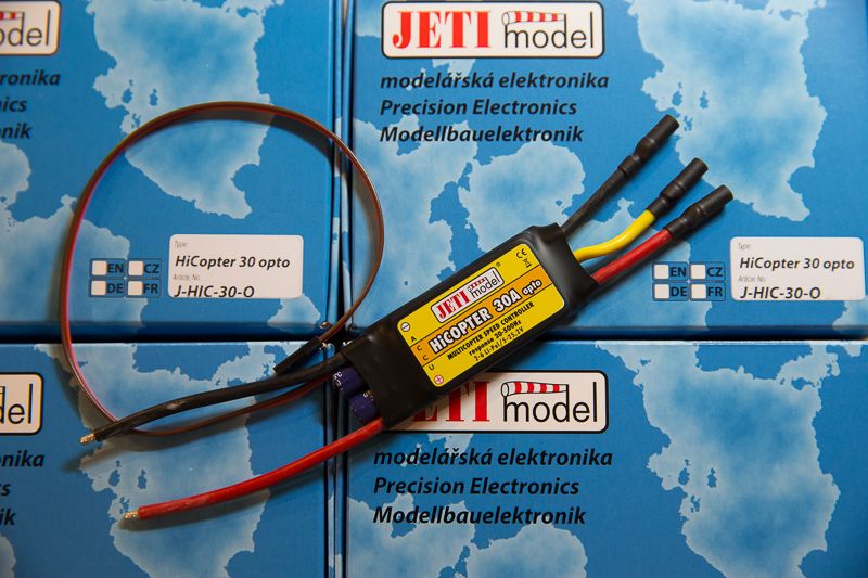
The ESCs are delivered in a nice box. The motor connections are the usual bullets, but with the handy flexibility of extension wires (as opposed to being soldered to the board). The power and signal wires are a comfortable length.

There are no settings for the HiCopter ESCs. There is no throttle calibration, no programming card, and no USB interface. Generally speaking, this is probably a good thing.

Each speed controller is pre-set from the factory with settings optimized for use with multi rotor aircraft stabilization systems. HiCOPTER controllers accept a control signal with a frequency of up to 500Hz. This allows them to accurately respond to any RPM change required by the control/stabilization unit of the multicopter. The motor control signal is galvanically (optically) separated from the flight battery in all HiCOPTER speed controllers. HiCOPTER speed controllers do not require or allow any programming changes. The propeller brakes are already switched off, the cut-off voltage is pre-set to the lowest possible level (depending on type) and the motor timing is set automatically by the speed controller. If you need to change the direction of rotation, simply swap any two of the motor wires.

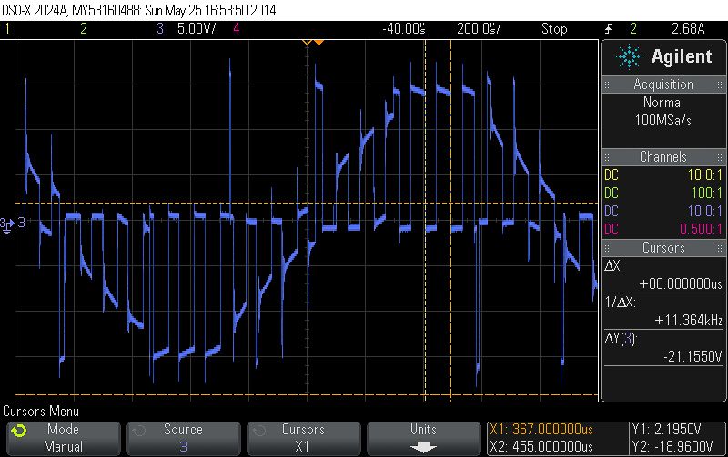
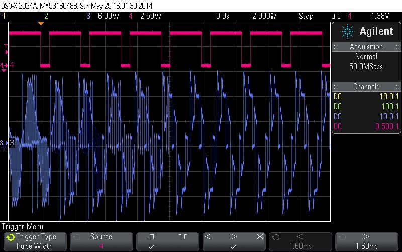
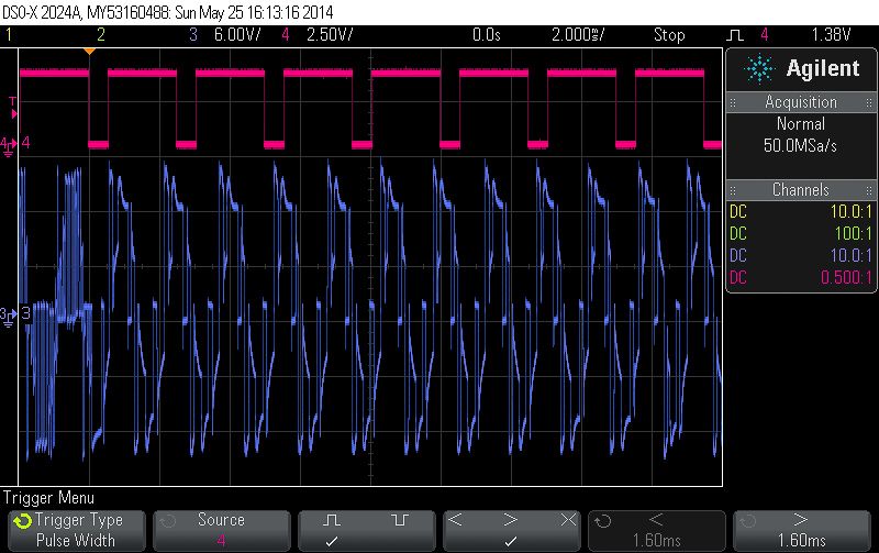
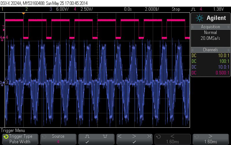
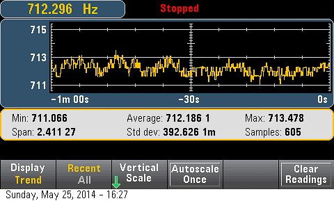
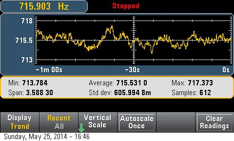
The 500Hz frequency response is nice, but typical (more on this later). More impressive is the optical separation of the signal side from the power delivery side of the ESC. ESCs tend to be marketed as “opto” when they do not output 5 volt power over the servo connection. But some “opto” ESCs produce their own 5 volt operating power from the main ESC power connection. This sounds reasonable until we realize that the connection can introduce noise back into the servo wires. You can’t just clip the voltage wire to fix the problem in many cases because the noise will be present on the ground wire too.

Thankfully, the HiCopters are true “opto” ESCs. They provide no power on the servo connection cable and require a 5v supply to operate. Most flight controllers will provide the needed power over the servo cable with no issues. This is a very nice feature, and is not to be assumed in just any “opto” ESC.

One almost ritualistic task — throttle setting — is noticeably absent. You shouldn’t care about this. Most flyers set ESC throttle endpoints incorrectly anyway, at least judging by what I see online. The basic problem is that people tend to set throttle with a direct connection to the radio receiver. Some even build special cables for this. In actual use, however, the flight controller is talking to the ESC, and will have its own independent throttle endpoints that need not match those of the radio. If your motors start when you want them to start, stop when you want them to stop, and deliver enough peak power to satisfy your flight demands then the throttle setting is just fine. The flip side of this is that you can’t really screw things up too badly by setting throttle endpoints incorrectly.

Many other ESC options are either anachronistic or confusing to the user. Sure, lipo destruction is bad, but worse is my copter falling out of the sky because the ESC is deciding to save the battery. It’s nice that the HiCopters have voltage cut-off preset to “the lowest possible level”. I would prefer no voltage cutoff at all. Admittedly, low-level cutoffs are often so low as to be effectively irrelevant, assuming the ESC correctly identifies the cell count of your lipos. The big worry is that the ESC misinterprets your lipo cell count and then cuts power inappropriately. In practice, I can’t get this to happen so I suppose it’s not worth worrying about. Nonetheless, it would be nice to see an ESC maker eliminate this feature altogether.

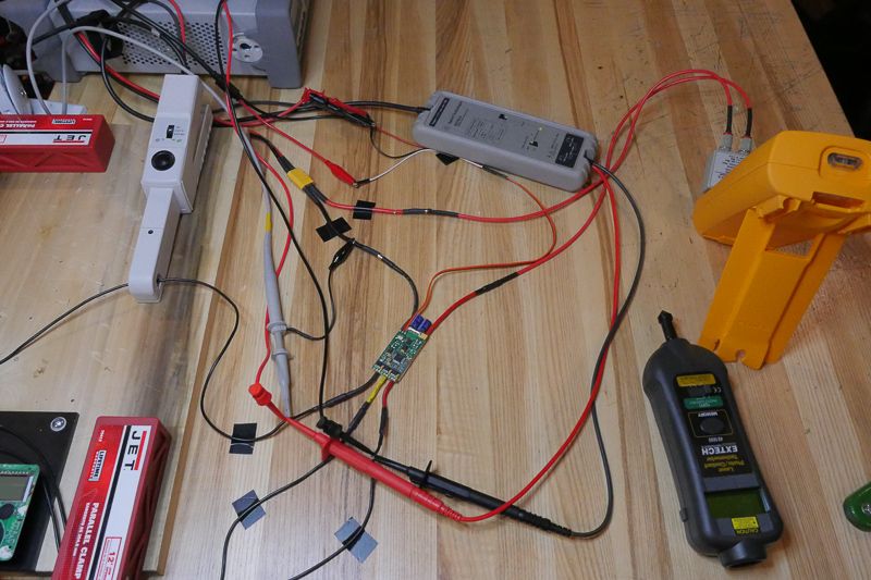
In sum, on specs and in actual use these are high-quality ESCs that perform well. But that’s no reason not to drill down on performance details. With modern multirotor flight controllers, the user only interacts with the ESC indirectly, and it is almost impossible for the typical flyer to separate the flight controller from the performance of the ESCs. This review attempts to get at a few direct measurements of ESC performance. Please comment on whether you find this helpful and if any additional metrics would be desirable.

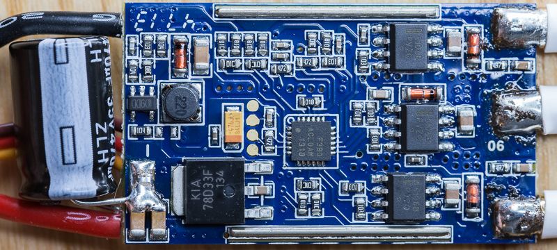
This review continues below with a section on how ESCs function (using the HiCopter ESC as example), followed by analysis of the HiCopter ESC as compared to a T-Motor 30A Pro Opto ESC and a Castle Creations Phoenix Talon 35A ESC.
 
Last edited by a moderator:

econfly

Member
PART 2: ESC DETAILS

An ESC’s job is to take DC power from your battery and convert it to 3-phase AC power for a brushless motor. In addition, the ESC responds to throttle input to regulate how fast the motor spins. All of this is accomplished imperfectly. The 3-phase AC output power is not a pure sine wave. The output voltage is not adjusted directly, but via pulse width modulation (PWM). Periodically, the ESC is monitoring the back feed from the motor to determine when best to fire the next pulse. This necessarily limits the ability of the ESC to fire the motor at full power.

We have two completely different forms of PWM at play in an ESC. On the input side, via the servo cable, a simple PWM signal is telling the ESC how fast to spin the motor. That PWM control signal looks like this:

https://vimeo.com/96638272

Rather than drive the ESC with a radio/receiver combination, I chose to use a function generator to produce the necessary pulse width modulated control signal. This allows both precise throttle input control and the ability to program sequences of throttle movements.

While the video illustrates how frequency does not affect interpretation of the PWM signal, the frequency does determine the rate at which the signal can change (the faster the pulses arrive the more quickly a change in pulse width can be identified). Because the typical pulse width ranges from 1 to 2 milliseconds, the upper limit for PWM signal frequency is about 500Hz — i.e., you can only fit, at most, 500 2-millisecond pulses into a single second. For reference, a Futaba 7008sb outputs PWM at 66.7Hz (a pulse every 15ms) while a DJI Naza sends PWM to ESCs at 400Hz (a pulse every 2.5ms).

The second (and very different) form of PWM at use in an ESC is on the output side, where the 3-phase AC power is chopped on and off repeatedly to control the effective output voltage.

https://vimeo.com/96638913

The three phases shown in the video are relative to the battery ground. The wave voltage is limited at the peak by the DC source input voltage (I am testing at 14.8 volts, or 4s power). You can see the modulation (the gaps between power on and off) fall away at full throttle. These three waves do not look like alternating current. But the relative voltage between each of them is what really matters, and to see that we can look at two of the waves relative to the third.

https://vimeo.com/96640004

It’s pretty obvious that the frequency of approximated AC voltage is related to motor speed. The phases compress when the motor speed increases. If you know the frequency of the AC wave, then you know the RPM of the motor (the relationship depends on the motor’s pole count).

The second part of the video above shows a comparison of the two phases in what is called a Lissajous pattern, where the voltages associated with a pair of waves are plotted against each other. Around the edges we can see common characteristics of two waves with matching frequency, yet out of phase with one another in typical alternating current fashion. Interior is all of the work related to pulsing the power (this drops out under full throttle). Perfect AC sine waves have an oval Lissajous shape, and we can see that the ESC is approximating that shape with linear segments — this is another way of seeing that the wave is capped at top and bottom with linearized segments in-between.

This last video shows a view of a single wave in three ways. The top two measures on the scope are showing the absolute and relative voltages presented in the prior video clips. The bottom (green) curve shows current flow along the single phase.

https://vimeo.com/96640727
 
Last edited by a moderator:

econfly

Member
PART 3a: MEASUREMENT and COMPARISON

Here is the HiCopter 30A Opto ESC with the shrink wrap removed, on the bench, and ready for analysis. You can see a current probe at upper left, a standard 10:1 passive probe at mid-left, a differential probe at upper middle, DC current being measured by a Fluke meter at right, and a laser RPM gauge at lower right (more for fun, than anything practical — RPM is best measured on the scope). As seen in the video segments earlier, the probes are connected to an oscilloscope, while AC current output is being measured by a bench multimeter.

BENCH_zpsc02d984a.jpg


Output PWM Rate

Fundamental to the ESCs function is the modulation of output power in order to raise and lower effective AC voltage. So, how fast does the HiCopter ESC perform this modulation? We can see the answer by looking carefully at the waveform:

JETI_res_zps7e117eb8.jpg


The time to complete an on-off cycle is 8kHz. The T-Motor ESC does the same at 12 kHz:

TIGER_res_zps0310cb61.jpg


The Castle ESC runs just under 12kHz:

CASTLE_res_zpsc6ae0137.jpg


The Castle ESC allows three settings for output modulation. The default is 12kHz (though I am reading a slightly slower frequency above), with an option for 8kHz and 16kHz.

Faster is not necessarily better here, though too slow could certainly be a problem. The ideal output PWM rate is related to motor timing. My test motor is a 700kv T-Motor MN3510-13, with 14 poles. All ESCs performed well with no timing issues.

Output Resolution

Consider a steady and perfectly smooth throttle increase. Do we get a similarly steady and perfectly smooth increase in motor speed or is the output delivered in jumps from one level to the next? Think of this as the number of different speeds an ESC can produce — steps or gears, if you will. This is very difficult to identify in practice, but could be the notion some have of an ESC being “smooth” or “locked in”.

The idea is to slowly increase the throttle, in a steady and consistent way, and then see how the ESC increases motor speed. To do this, I used the wave generator to deliver a steadily rising throttle over a 50 microsecond interval — i.e., a 1/20th of a millisecond change in pulse width. This very gradual throttle increase was delivered over a period of 50 seconds. The oscilloscope was set to trigger on every cycle of ESC output, with the trigger delivered to the bench multimeter which was set to measure frequency. This frequency, ultimately, determines motor speed (RPM).

All of that means I just raised throttle very slowly and measured the impact on output RPM. Here is how the HiCopter ESC performed:

JETI_step_zps43e160fc.jpg


That is, by my eye, 8 or 9 steps of speed increments over the period of the test, with some jumps being larger than others.

But we can see that T-Motor’s ESC steps up motor speed in much finer increments — more than twice as smoothly:

TIGER_step_zpse027e635.jpg


Castle’s ESC has an amazing, almost perfectly smooth response:

CASTLE_step_zps81f35a43.jpg


What does it mean? Castle wins. There is no question here that a smooth output response is desirable. Now to be practical, I didn’t have the feeling that the HiCopter was faulty in some way in the test flight. The reason is that even 8 or 9 steps per 50 microseconds of PWM width is about 160-180 steps in total over the 1-2ms PWM range. Even if some of those steps are lost because the motor arms above 1ms and tops out under 2ms, there are still well over 100 output power steps in the middle. In reality, that may well be plenty. In principle, however, smoother output is more desirable, and the Castle ESC is the clear winner here.
 

econfly

Member
PART 3b: MEASUREMENT and COMPARISON

Punch It

What happens when you hit the throttle? Does the ESC deliver power quickly?

To find out I started at mid-throttle and punched in an instant shift to full power. The scope was set to trigger on the jump in the PWM input signal — the moment the full-power throttle input arrives. In the scope screen capture below, the little orange triangle at the top left is the point where the throttle is punched. The HiCopter responds about 8ms later (the divisions on the screen are 2ms) with a noticeable change in the output waveform. Note that the frequency does not appear to change much — that takes time and is motor dependent. Here we are looking for the ESC’s ability to alter the output pulsing (and timing) in response to a rapid throttle increase:

JETI_punch_zpse37a2562.jpg


T-Motor’s ESC delivered near instantaneous change:

TIGER_punch_zps8b3aa265.jpg


Castle lagged considerably (still measured in milliseconds, but just quite a bit longer than observed with the other two ESCs). You can’t see it respond at this magnification:

CASTLE_punch_zps9c80500b.jpg


Tiger wins the responsiveness test, but there is a case to be made for HiCopter’s and even Castle’s results. This is where the flight controller is a critical partner in perceived performance. If the controller is smart enough to deliver throttle requests in a way that optimizes a combination of responsiveness and battery life, then you want the ESC to be as responsive as possible. But, if the controller is not smart enough to limit itself in an optimal way, then you might want an ESC that limits responsiveness. This is an area that requires much more work to reach definitive results, and those results would depend on both the ESC and the flight controller combined.

Efficiency and Consistency

All three ESCs delivered almost exactly the same efficiency, with very minor consistency differences. I set the throttle at a level that resulted in 7.5amps of input DC current consumption. Then, using the scope to trigger on the output wave I examined frequency over about one minute of time. Each ESC delivered nearly the same frequency mean (keep in mind that fixing the input current at 7.5A is not an exact task given variation and measurement issues), with fairly trivial differences in output variation. The point to take away from this is that you shouldn’t expect any of these ESCs to delivery longer flight times or smoother power at fixed throttle. Performance differences are trivial.

HiCopter:

JETI_noise_zpsd61e89c7.jpg


Tiger:

TIGER_noise_zpsaef3c055.jpg


Castle:

CASTLE_noise_zpsb650f600.jpg
 

econfly

Member
PART 4: COMPONENT DETAILS

One might expect the design of ESCs to be so standard that makers tend to pick the same hardware, with differences limited to software and packaging. That is not exactly true, though we can see that design among the three ESCs examined here does have some common elements.

All have capacitors on the main power input path, a microcontroller, and the expected FETs for switching output power. The HiCopter is using an Atmega microcontroller, and while it’s hard to see in the photo, under a loop I can see that the HiCopter has IOR FETs. Tiger is using a SILABS microcontroller and Toshiba FETs, while Castle has a SILABS microcontroller (different than Tiger’s) and Infineon FETs.

As a ballpark figure, the various components in these controllers might run around $10 or less — about what you would expect when the finished product sells for around $50 - $60.

All three ESCs had heat sinks over the FETs. I removed them for the photos below.

HiCopter:

JETI_a_zpsf5677f8d.jpg

JETI_b_zpsf66d6a3b.jpg


Tiger:

TIGER_a_zpsc5c178a1.jpg

TIGER_b_zpsd0801e3c.jpg


Castle:

CASTLE_a_zps3f6f9bbc.jpg

CASTLE_b_zps95ca177f.jpg
 

econfly

Member
This was a tough review. At one level there is a very simple conclusion: JETI's HiCopter ESCs work as promised and offer simple installation with no needed user settings.

But as we can see, there is a huge amount of complexity and detail that I have only begun to explore. This review is much longer than I anticipated it would be, yet there is a lot that I omitted, and surely more that I haven't even considered. A big challenge in a review like this is offering useful information on a complex topic, while not turning readers away with too much exposition (e.g., the second post above) or too little context (e.g., everything I didn't say or explanations I hurried or skipped).

Please offer up any questions, comments or criticisms. What do you want to know about ESCs? And what would you like to see in future reviews?
 
Last edited by a moderator:

Bartman

Welcome to MultiRotorForums.com!!
Thanks so much for both the review and for developing the set-up to test ESC's more thoroughly than I've seen anywhere! Can't wait to see what else gets uncovered now that your test bench is up and running.

Very nicely done review.
Bart
 

Quinton

Active Member
A big challenge in a review like this is offering useful information on a complex topic, while not turning readers away with too much exposition

Thank you for this review and the time taken to do it, and trying to demystify the differences in ESCs.
It is much appreciated.
Now back to the top again to read over the information again to let it sink in.

Would be great if some kind of comparison in the future could be done with these ESCs comparing them to the likes of freewheeling ones like Herkules or similar.
 

Motopreserve

Drone Enthusiast
Great review! Very well written and thorough. While there was much that went over my head, this is something I'm sure I'll read a few times to grasp fully.

I know this would be of-topic to the review here, but in terms of demystifying the ESC in general, I'm wondering if there is some type of conclusive test that can be done to determine whether additional capacitors should be used when running longer wires to the PDB (ESC mounted on the motor ends of booms).

Also, do you have an opinion on which set of components used in the 3 ESCs above were the superior choice? Or are they all in the ballpark, quality wise?
 

Av8Chuck

Member
This is also over my head but I can certainly appreciate the effort that went into this presentation, great work.

Im also curious about running longer power wires to the ESC to mount the ESC below the motor.
 

econfly

Member
Great review! Very well written and thorough. While there was much that went over my head, this is something I'm sure I'll read a few times to grasp fully.

I know this would be of-topic to the review here, but in terms of demystifying the ESC in general, I'm wondering if there is some type of conclusive test that can be done to determine whether additional capacitors should be used when running longer wires to the PDB (ESC mounted on the motor ends of booms).

Also, do you have an opinion on which set of components used in the 3 ESCs above were the superior choice? Or are they all in the ballpark, quality wise?

I think there is some neat work that could be done regarding the need for capacitors. One way to get at it is to stress test the ESCs over some period of time, but with different capacitors installed (de-solder the capacitor(s) and add incrementally to see how the performance is affected). I'll think of other/better ways to get at this issue and will plan to do some testing in the future.

As for the components, it's close. The major parts are the capacitors, the FETs, and the microcontroller.

All 3 ESCs are using 35 volt capacitors. HiCopter is using a pair of 120 microfarad United Chem-Con capacitors in parallel (240 μF total). Tiger is using a single Rubycon 470 μF capacitor. Castle is using a pair of 220 μF Panasonic capacitors in parallel (440 μF total). Based just on market prices, the Panasonics are the most expensive, though I would say any of these choices is fine. The choice of two smaller capacitors over one larger one is perhaps an advantage for HiCopter and Castle.

All 3 ESCs are using N-Channel MOSFETs. HiCopter is using International Rectifier, Tiger is using Toshiba, and Castle is using Infineon. I don't know enough at this point to pick a winner here. Superficially, the specs appear in the same ballpark among them.

On the microcontroller front I am more comfortable identifying the best component. Castle is using a SiLabs F541, 50MHz, 8-bit controller that offers 12-bit ADCs. Tiger is also using SiLabs, but is running a cheaper and slightly less capable F390 (50MHz, 8-bit, but with 10-bit ADC capability). HiCopter has an Atmel Atmega 8A AU microcontroller that runs at 16MHz, is 8-bit and has 10-bit ADC capability. All of them can do the job, and the cost only runs from a little over a dollar for Tiger's controller to about $2.80 for the F541 in the Castle ESC. But if I had to pick one, I would take the F541 in the Castle.

To be sure, it's a tight race among these three when it comes to components. As I mentioned in the review, the parts for one of these ESCs would likely come in around $10. Given the very tight performance results, and differences almost certainly attributable to software, I think these ESCs are really differentiated by design features and the software they run.

One point I would push here is that most multirotor users don't need a BEC on their ESC. If you do have a need to pick up 5 volts I would simply solder a stand-alone BEC to the main power supply. There is no need to be using the ESCs for this purpose.

On top of that, I really like the HiCopter ESC's design that truly separates the motor drive power from the input signal (servo) connection. Tiger's ESC, by contrast, does not offer the benefits of a BEC (no 5v output on the servo connection) but it does NOT optically separate the servo connection from the main power / motor drive (there is continuity from the 3-wire servo connection ground to the main power ground). That offers the possibility of noise coming back into the servo connection. That may turn out to be no big deal, but why have it when it can be eliminated like it is in the HiCopter? The Castle ESC I tested has a BEC, so there you at least get the benefit along with the potential for noise on the signal ground.
 
Last edited by a moderator:

Bartman

Welcome to MultiRotorForums.com!!
This is also over my head but I can certainly appreciate the effort that went into this presentation, great work.

Im also curious about running longer power wires to the ESC to mount the ESC below the motor.


I think the test for this would be to look at the voltage going into the motors while adding progressively longer leads to see if voltage spikes occur at the end of the pulse with longer wires compared to shorter ones. The capacitors are supposed to dampen out the spikes but it's a mystery as to if they're even happening given the many branches and routes for electricity to flow through a multi's power distribution network. I'd bet that the network acts as something of a big capacitor.

To be accurate the test would have to be done with four, six, or eight motors all running on similarly long leads while measuring voltage of one motor input circuit
 

A couple of years ago a Castle technician told me that the long power wires are bad for the esc capacitors and if I intend to extend the wires I should add extra cap's.
 

Motopreserve

Drone Enthusiast
Bart, I agree.

And I guess the constant for the test could be the typical lead length provided by the manufacturer with stock motor leads. I suppose that different ESCs may react differently??? So to keep it most simple, maybe the most common ESC could be used? An f30a or something common and not considered particularly "high end?" Or should it be something better?

RRH:

i think the problem is that most of us have been told, or at least read, that they will/will not make a difference - but rarely why. At least that's true in my case. If this test could serve as clarification , and be conclusive, we'd all be better for it.
 
Last edited by a moderator:

econfly

Member
Testing on a multiple motor setup could be a real challenge. But I think the point is a good one -- there is nothing special about the connection between the end of the ESC wire and the power distribution point. Beyond that we have yet more wire, other ESCs, and even the connection path from distribution back to the battery. All of that will have some capacitance, as Bart says. In addition, each ESC will be creating voltage spikes out of sync with the others, and there must be some natural dampening that occurs from having all of them connected to the same power source. Ultimately the problem (if there is one) varies depending on the build details.

Of course there are examples out there where builders are putting ESCs under motors. The DJI S800 Evo is an example, and their ESCs use a pair of 50v Rubycon 220 μF capacitors in parallel. That doesn't mean they got it right, but there are plenty of Evo owners out there and I haven't seen any complaints about ESC failure or blown capacitors.
 
Last edited by a moderator:

Motopreserve

Drone Enthusiast
Econ,

do you think that it would provide valuable info if you tested just one ESC/motor combo with and without the additional caps? My question cones more from a standpoint of whether they are in fact needed or not at all - since the info online is all over the map - and none that I've found had nearly the detail and inclusiveness that your review here did. So unfortunately, while I'd like to think everyone is correct, I find that unlikely :)

im about to mount some ESCs out on the booms. There are people with the same frame doing it without caps - because the info is inconclusive. I've flirted with adding the caps because I'm at the point of "why not" or "what harm..." since I can't get a conclusive answer either.

If this turns out to be too much, or there are too many variables - I appreciate you even considering it. Look how easy it is to offer up so wine else's time and test bench... :)
 

econfly

Member
Econ,

do you think that it would provide valuable info if you tested just one ESC/motor combo with and without the additional caps? My question cones more from a standpoint of whether they are in fact needed or not at all - since the info online is all over the map - and none that I've found had nearly the detail and inclusiveness that your review here did. So unfortunately, while I'd like to think everyone is correct, I find that unlikely :)

im about to mount some ESCs out on the booms. There are people with the same frame doing it without caps - because the info is inconclusive. I've flirted with adding the caps because I'm at the point of "why not" or "what harm..." since I can't get a conclusive answer either.

If this turns out to be too much, or there are too many variables - I appreciate you even considering it. Look how easy it is to offer up so wine else's time and test bench... :)

I'll do it, no problem. Since we are in the HiCopter review, I'll take one of their ESCs and start in.
 

Motopreserve

Drone Enthusiast
I'll do it, no problem. Since we are in the HiCopter review, I'll take one of their ESCs and start in.


You are the man!

Some of you guys probably have one already, but I'm in the process of putting together a bench motor test rig. I'll be testing the ones I have on hand, but then will be more than happy to chip in to the greater knowledge base if people are looking for data on specific motors.

and stay tuned for an article/post by the boys at KDE Direct explaining and clarifying subjects such as: pancake, high pole count, advantages and disadvantages of these choices etc.

if we keep this up - Bart might have to open a "tech section" :)
 
Last edited by a moderator:

econfly

Member
You are the man!

Some of you guys probably have one already, but I'm in the process of putting together a bench motor test rig. I'll be testing the ones I have on hand, but then will be more than happy to chip in to the greater knowledge base if people are looking for data on specific motors.

and stay tuned for an article/post by the boys at KDE Direct explaining and clarifying subjects such as: pancake, high pole count, advantages and disadvantages of these choices etc.

if we keep this up - Bart might have to open a "tech section" :)

Thanks. I'm having fun with this stuff. Look forward to your motor reviews. Are you building or buying a test rig? My bench motor setup is just a relatively cheap thrust meter (link). It works, but on my project list is a plan to build a much better solution. I haven't started that project yet --- probably won't for a while.
 
Last edited by a moderator:

Motopreserve

Drone Enthusiast
Thanks. I'm having fun with this stuff. Look forward to your motor reviews. Are you building or buying a test rig? My bench motor setup is just a relatively cheap thrust meter (link). It works, but on my project list is a plan to build a much better solution. I haven't started that project yet --- probably won't for a while.

Im going to be building one - but it will be fairly basic DIY. Nothing too fancy, but I'll be able to gather current, thrust, performance for various props etc. I'm really getting tired of incomplete (or often complete lack of) info for some of the motors. And then who knows how accurate it is...

this way I'll feel comfortable knowing that the chosen components should be safe/efficient working together from my own info - not relying on the sparse spec sheets found online.
 

Top